February, 2015
Vacuum Pump
I
think I've now accumulated enough reasons to build a real vacuum
pump setup. First, I've done some synthetic rubber casting of
small parts, and while the parts came out totally usable, they would be
cosmetically better looking if I did a degassing step before pouring
the resin. Degassing is done by subjecting the freshly catalyzed
resin to a vacuum, and would eliminate the pin holes and rough surface
texture on some of the parts.
More recently, on my Triumph TR6
rebuild project, I want to apply a new veneer to the original wood
dashboard. One good way to ensure a smooth and well bonded veneer
is with a vacuum press, which requires a good vacuum pump.
I did
a little research into commercial systems and found that in addition to
the vacuum pump itself, they often include a vacuum reservoir and a
vacuum sensor that is able to cycle the pump to keep the reservoir
charged, like an air compressor. Also like an air
compressor, there is usually an "unloader" arrangement so that the pump
doesn't have to start against a vacuum, but rather is allowed to come
up to speed before the pumping load is applied.
One really wonderful source of information (and parts) for these devices is at http://www.veneersupplies.com/pages/DIY__Vacuum__Press.html. Though
my system differs from theirs in a couple of aspects the
principles are all the same, and they have pretty good prices on some
of the pieces.
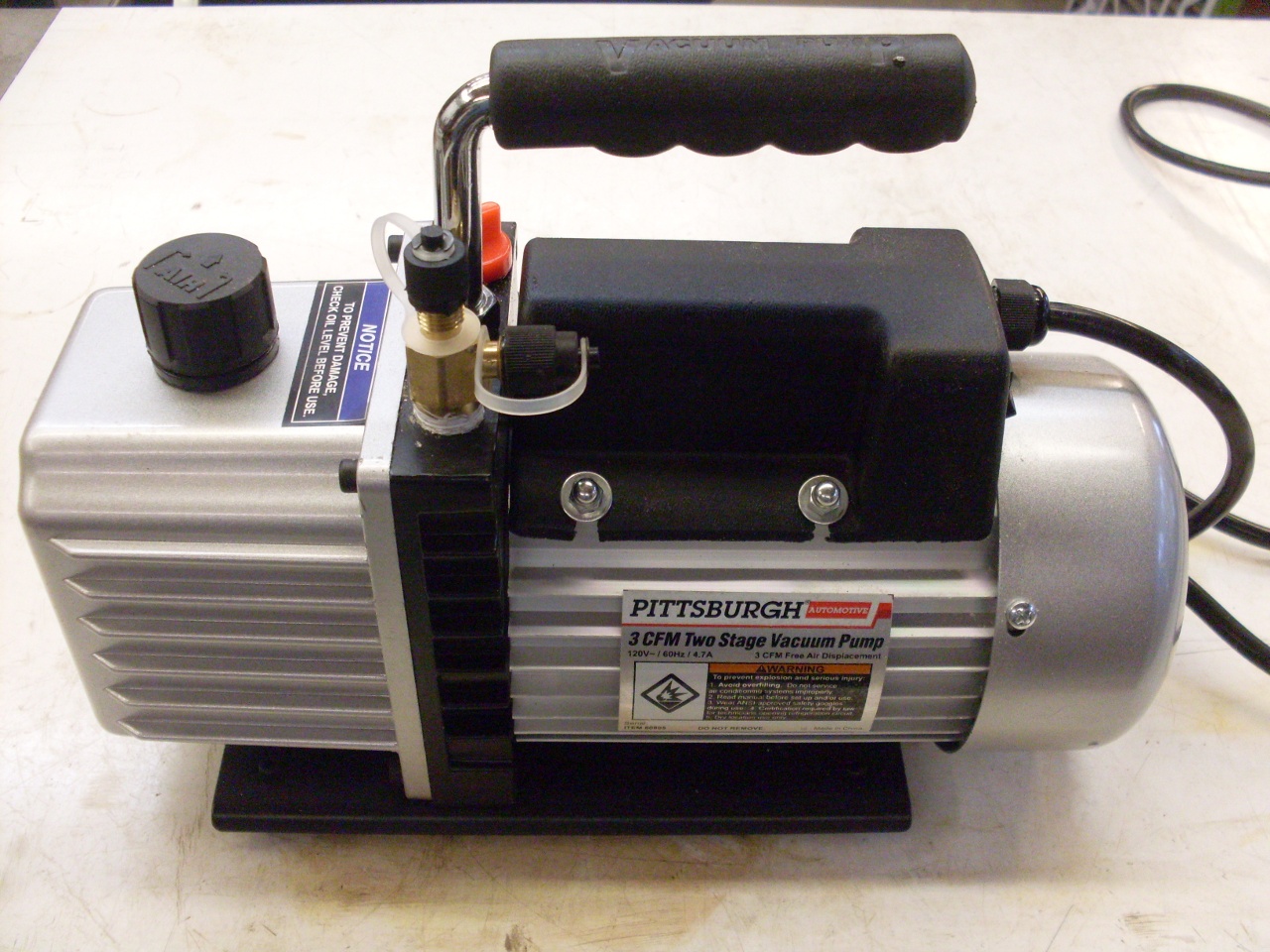
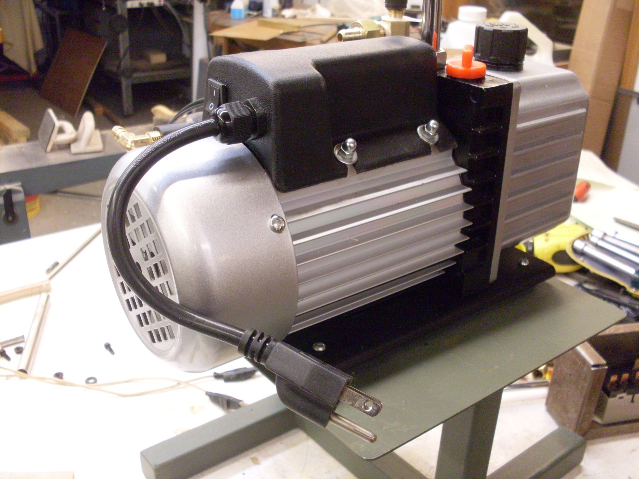
I started with a
3 CFM, two stage vacuum pump sold for evacuating AC systems. This
particular pump is fairly ubiquitous. I saw it sold under a
variety of brand names at prices that varied over a two-to-one range.
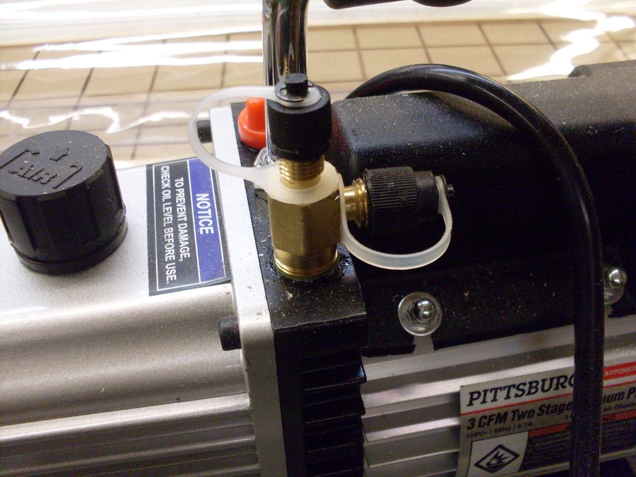
Right
off the bat, I hit a little snag with the pump. Since it was
designed for AC systems, it's two fittings were specific to that
application. The top inlet is a male flare, and the one on the
side is an 1/2" ACME, but what I wanted was a 5/16" hose barb. My
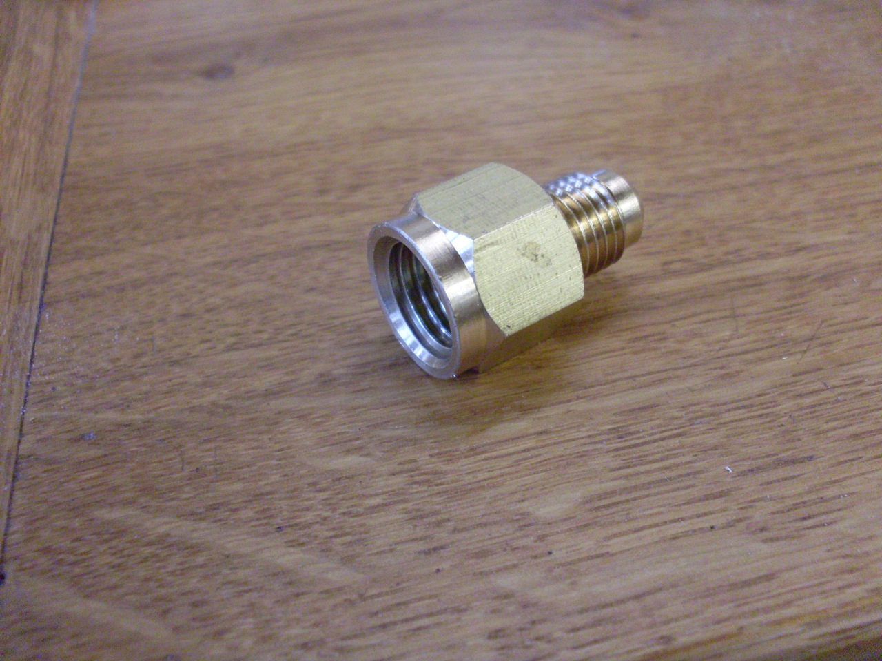
first thought was to just remove that brass fitting and replace it with
a barb fitting. That didn't work out since the fitting is also a
check valve. I found ways to make the transition with multiple
adaptors, but in the end, I just bought an ACME to flare adaptor, and
modified the flare part to a hose barb.

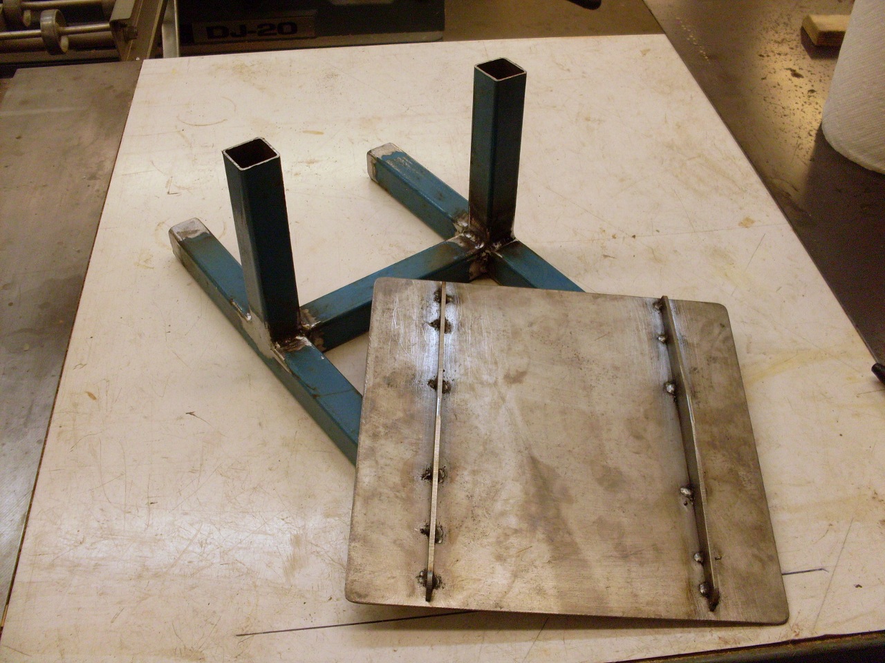
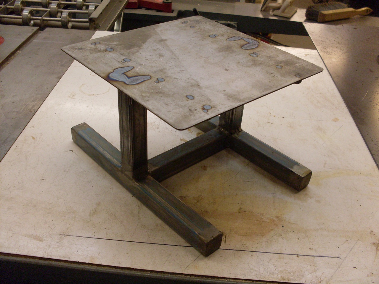
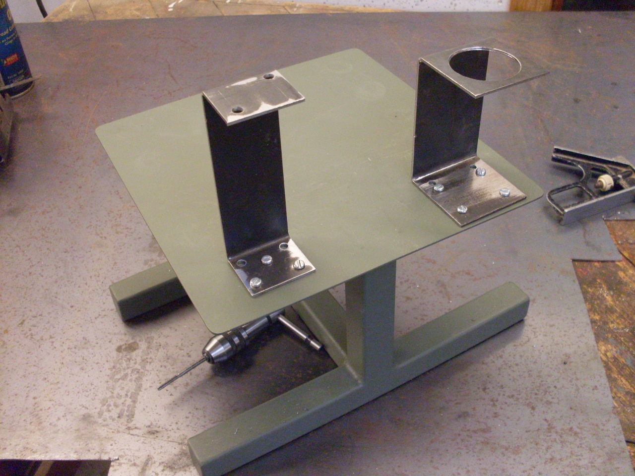
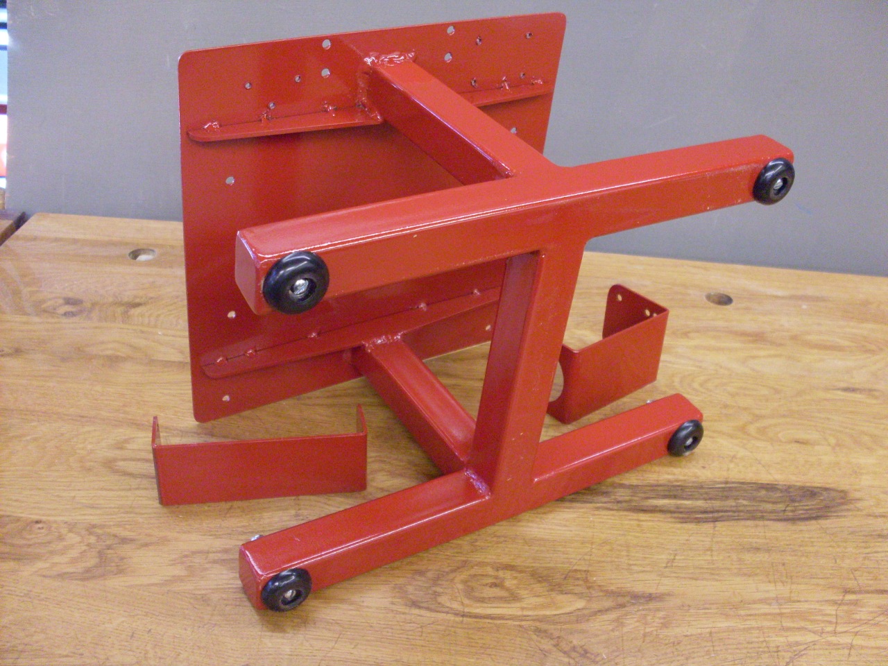
I
decided to build a frame with a platform that would hold the pump and
all the other parts of the system except for the reservoir, which would
be monted below the platform. This is a fairly common approach.
I found some 1 inch square tubing at a salvage yard, and I had a
chunk of 14 gauge sheet steel left over from something else.
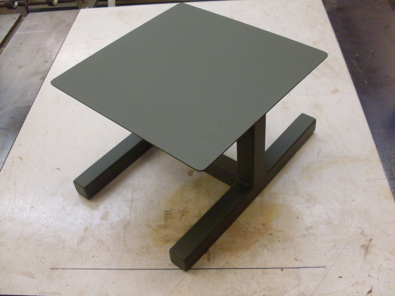
Wellded it up, cleaned it, and primed it.
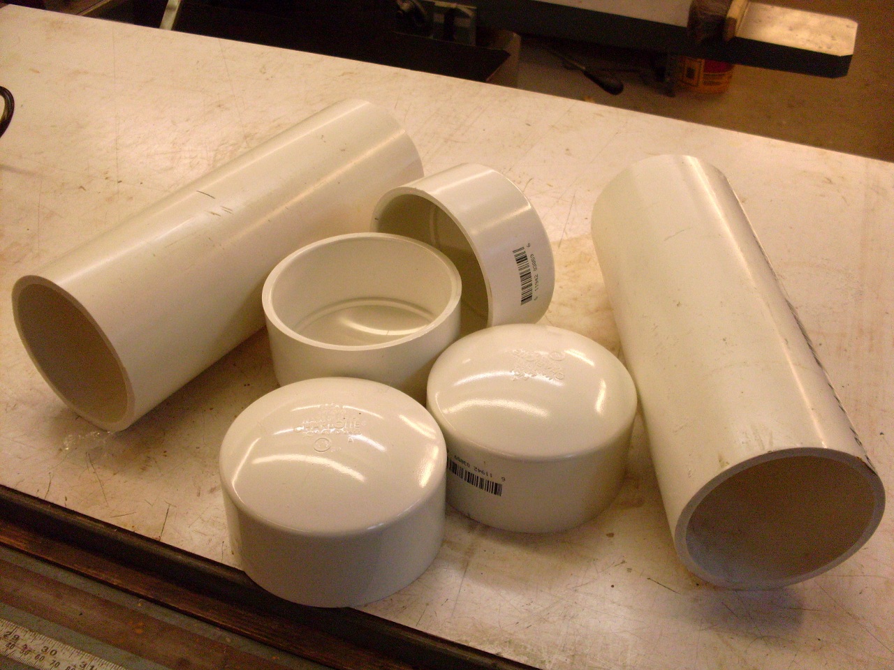
The
reservoir will be two pieces of 4 inch PVC plumbing pipe, each capped
on both ends. One thing I learned from this exercise is that I
had to drill a hole in one of the end caps for each tube. Without
the hole, the trapped air inside made seating the second cap
difficult.
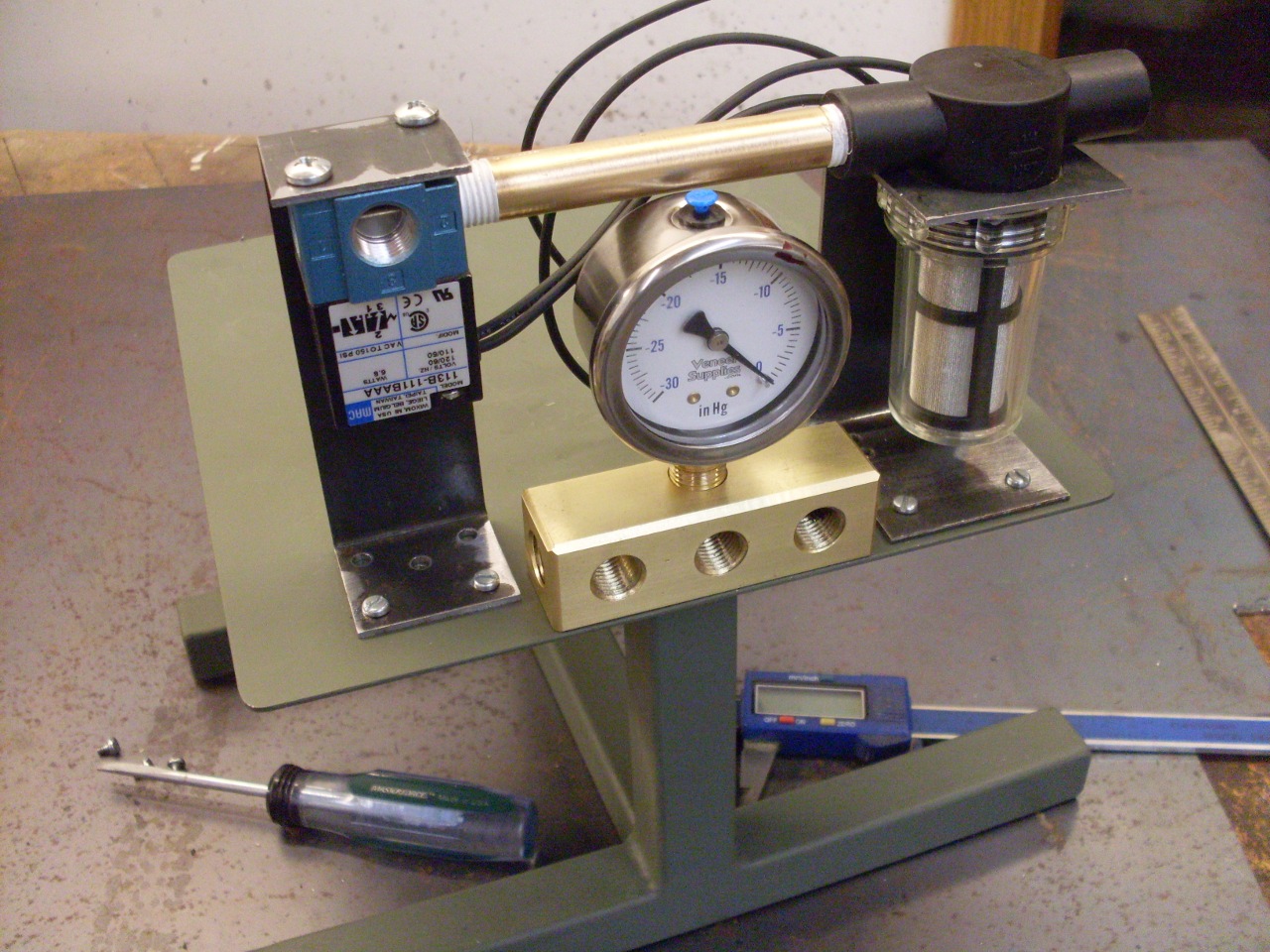
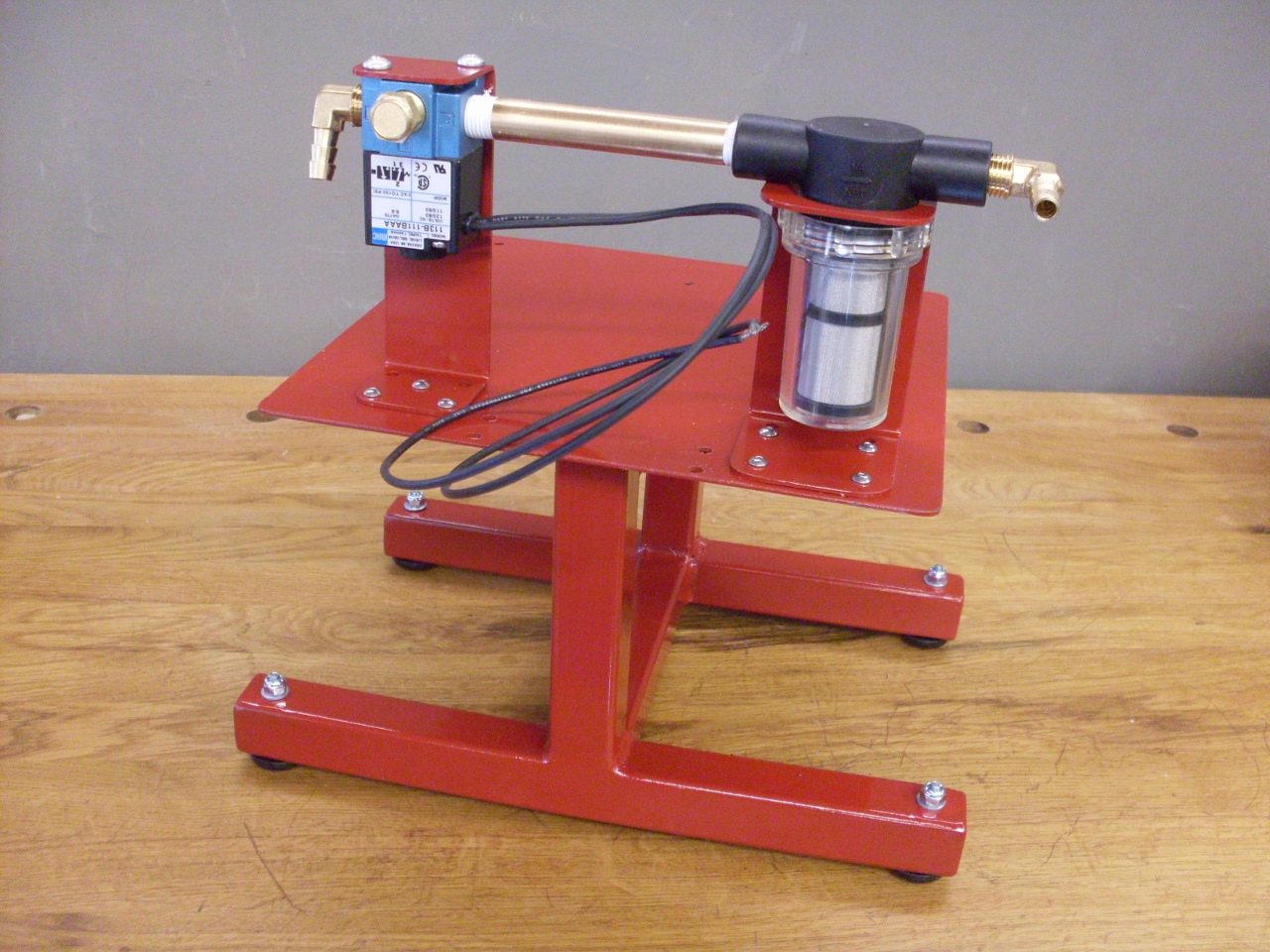
The
air plumbing goes on top of the platform. The air filter and the
unloader valve mount on brackets such that the connection between them
is a straight shot.
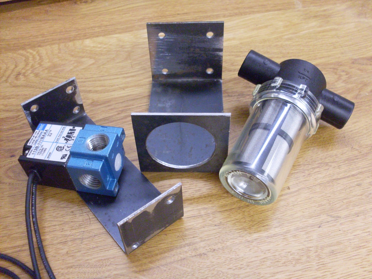

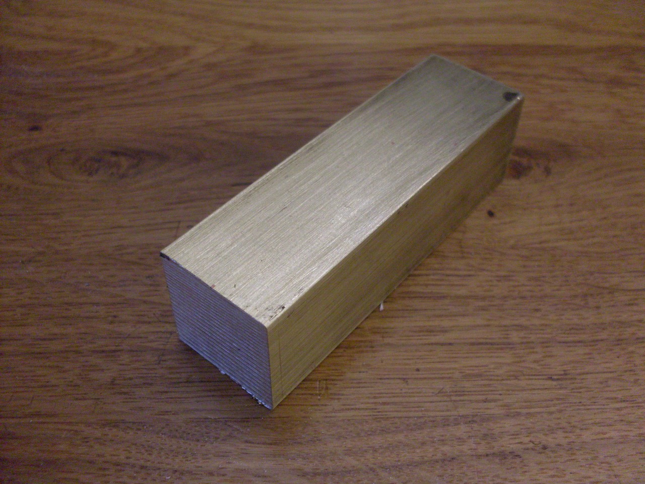
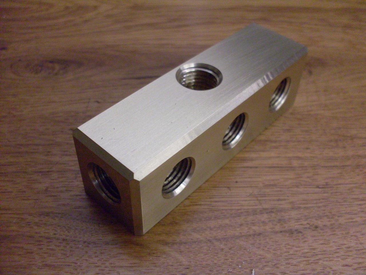
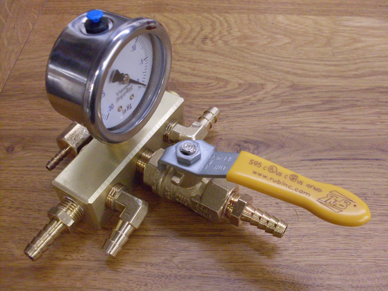
Rather
than having brass plumbing and fittings snaking everywhere, I made a
brass manifold for everything to connect to. It has eight 1/4
inch ports, including two that will be plugged. At this point, I
wasn't totally sure which ports were going to be used for what.
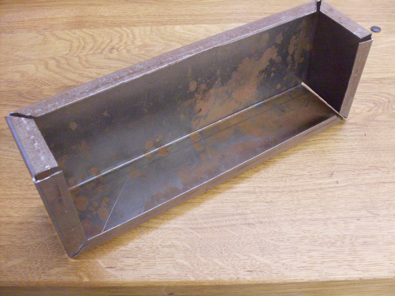
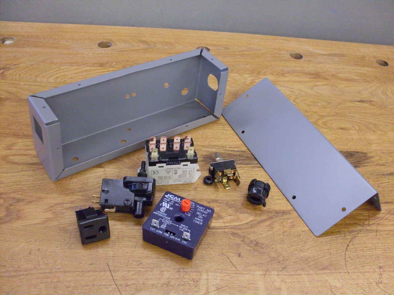
I
wanted to enclose the electrics both for safety and for a neater look.
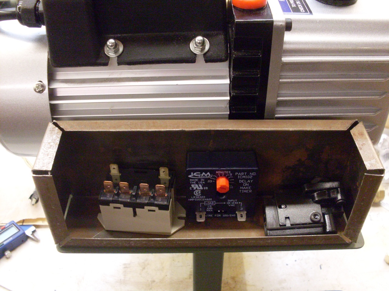
I made up this box to fit on the platform next to the pump, and
began to trial fit the components. From left to right, there is a
power relay (since the vacuum switch doesn't have quite the capacity to
handle the pump), a delay module (to delay switching the pump over to
the load), and the vacuum switch.
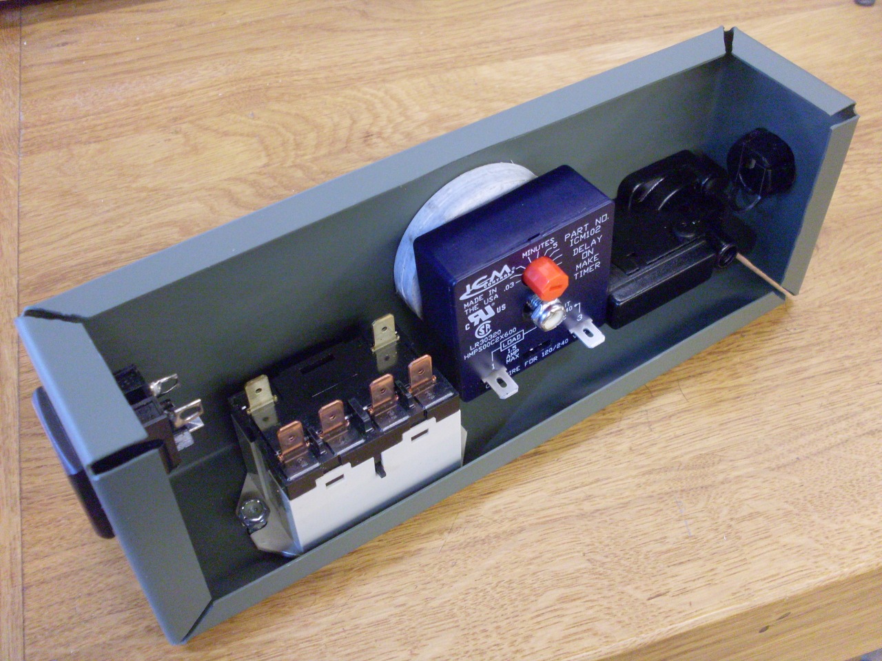
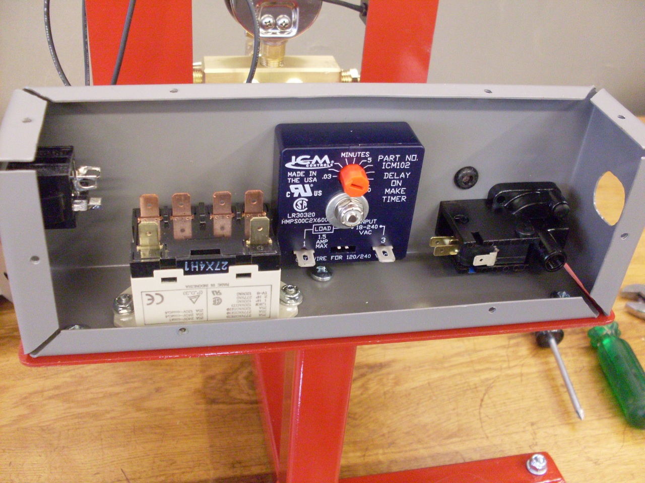
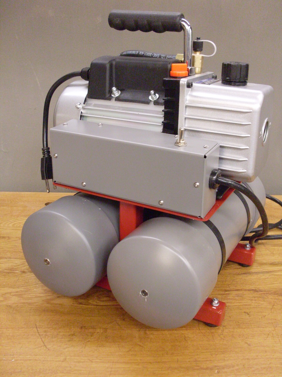
This
is the final layout. On the left end is an AC outlet for the pump
to plug into. I considered hardwiring the pump to tne box, but
finally decided that if I ever have to replace the pump, or want to
take it out for some reason, the plug would be handier. I did
shorten the pump's cord, though, so I wouldn't have six feet of cord to
find a place for.
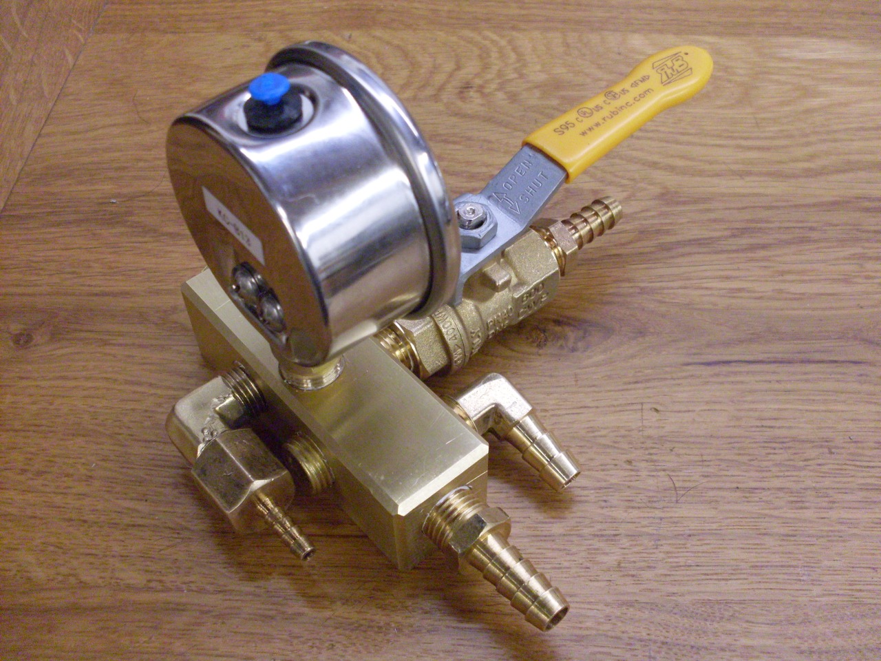
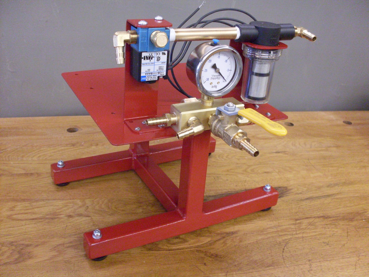
Here
is the final manifold setup. The vacuum outlet is in the middle
on the front. The reservoirs will connect to the right and left
of the outlet. the hose barb on the left goes to the pump, and
the barb on the back goes to the vacuum switch.
I painted the frame and brackets a nice cheery red, and added some soft feet.
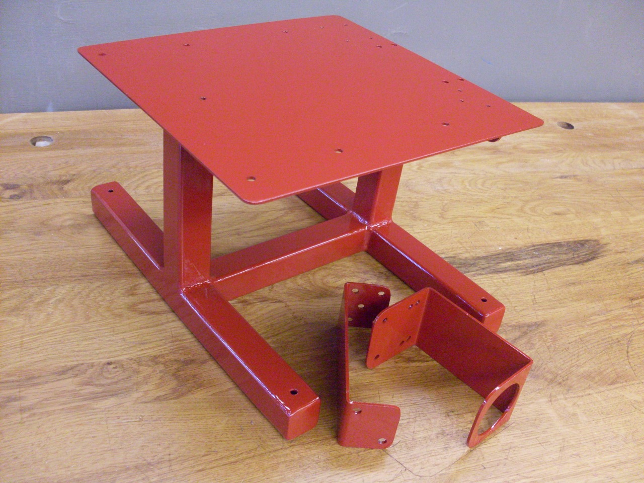
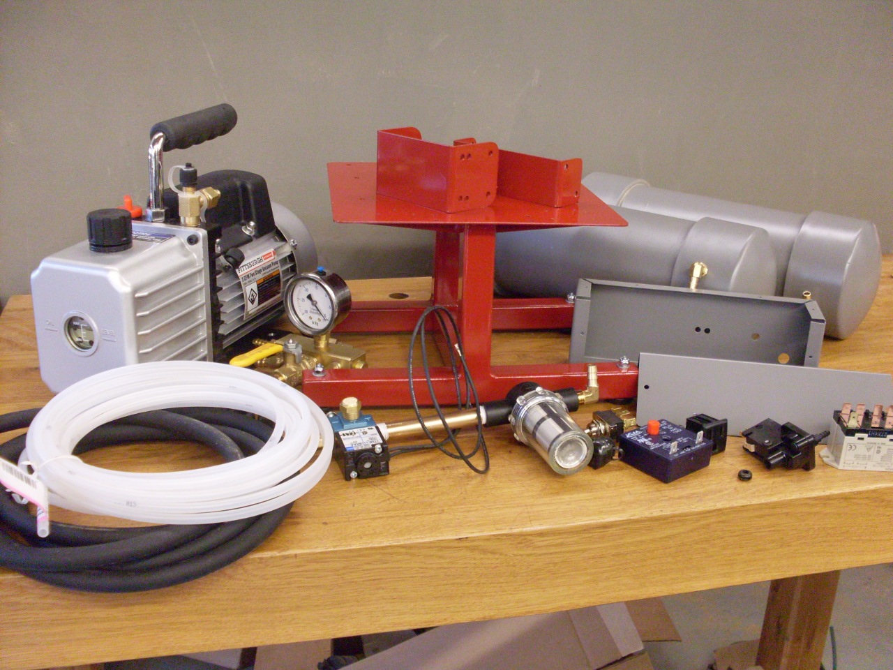
So here are all the parts that have to be screwed together to make a vacuum pump system.
Fist the brackets were mounted and the filter and unloader valve were added, followed by the manifold assembly.
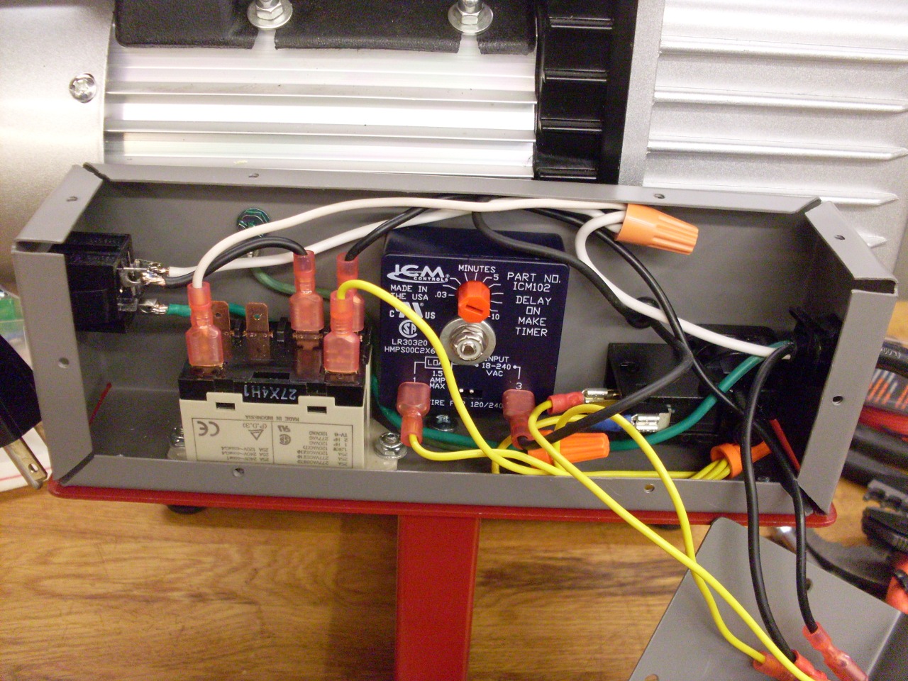
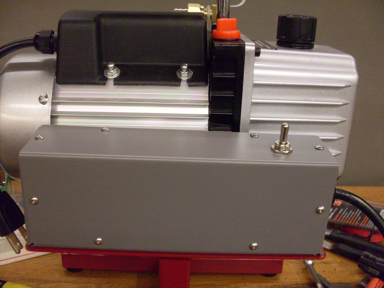
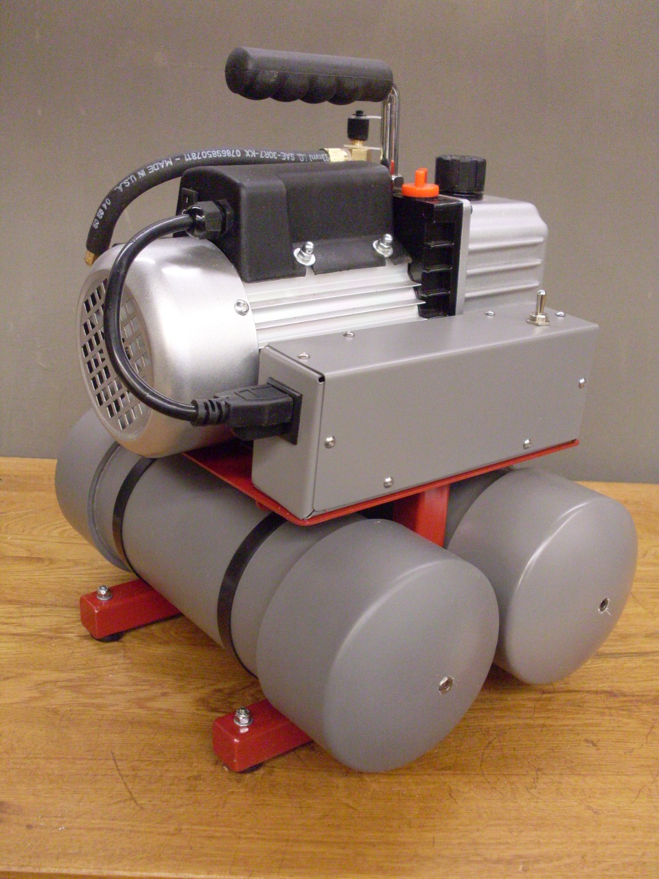
Then I mounted the electrics in the box and fastened the box to the frame.
Then wired the box and mounted the pump itself. The Continuous/Off/Auto switch is on the box cover.
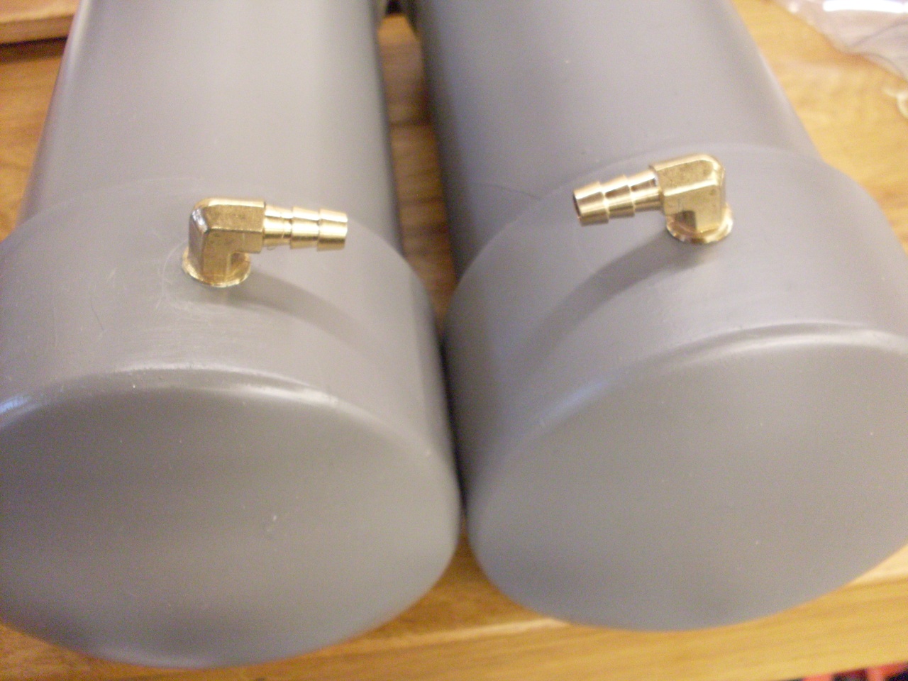
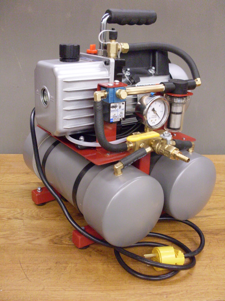
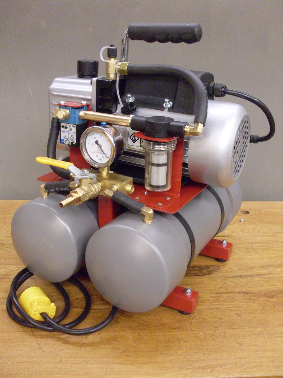
Mounted
the reservoirs with some serious duty cable ties, then finished the
plumbing with some vacuum rated 5/16" hose. Here's the final product:
After
moving one misplaced wiring connection, the pump ran great the second
time I tried it. The delay timer is set at about 2 seconds, which
seems to be plenty of time for the pump to get up to speed.
I'd really like to find a different timer since this one is
really more for the minute range, and I have to have it set almost at
its minimum.
I
did a quick 5-minute leakdown test, and saw no detectable drop in
vacuum, which means there are at least no gross leaks.
Now to see about making a vacuum veneering bag.
Comments to Ed at: elhollin1@yahoo.com